Visa version
Visa
< föregående
|
nästa >
Jämför
< föregående
|
nästa >
Lab2 wiki (en)

![]() IE1204.zip all course simulation files.
IE1204.zip all course simulation files.
Lab2 tutorial builds on Lab1 tutorial
You may need to repeat Lab1 tutorial to perform Lab2 tutorial.
Visit: http://www.linear.com/ to download and install the program LTspice on your own computer. You do not need to register if you do not want to. The installation is then "straightforward" as described on the website. The program is available for most operating systems, but this tutorial describes the appearance under Windows
Course simulation files
The program is installed on school computers in lab Ka-305 and in computer room Ka-309. In school you have to unzip the course simulation files in your server folder as H:\IE1204 . (at home you can unzip the files in any folder place).
You start LTSpice by doubleclick on any  *.asc - file.
(You can also start the program ![]() LTSpice from the start menu).
LTSpice from the start menu).
 If you click on the simulation icon in the program a simulaton will start with the settings we have choosen for you. Then you can simply proceed by changing values and other preferences to explore all the course circuits!
 IE1204.zip all course simulation files.
Simulation of sequency circuits

A sequential circuit can produce different outputs for the same input signal combination. The circuit has an internal "memory function" that takes into account what has happened previously.
To test such circuits must be able to generate sequences of signals. Since this is a course in Digital technology we choose to generate sequences with digital components!
The digital component that is commonly used for converting parallel to serial data is the shift register. The 74166 is such a shift register. The parallel 8-bit value is loaded into the input terminals and then shifted out serially.
Move the mouse over an input so that the pointer switches to the I-shape, right-click, and then write 1 or 0, to connect the input to the desired level of the voltage source.
The set is then shifted out serially. With more shift registers, we can generate longer sequences of input combinations. Voltage sources in the schematic emit pulses that control the shift register during the simulation. They do not need to be changed.
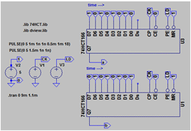
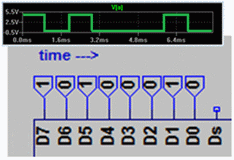
Latch with NOR-gates ( before lab Sequence circuits )

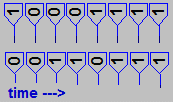
At the lab, you should connect, and test, a latch with NOR gates (7402). The input signals a and b shall comply with one five-step sequence as shown. This is how we are simulating the circuit.
Open the template file  sequence_test.asc and save it as
  sequence_latch.asc. The file contains two shift registers for the signals a and b. Edit so that the sequence becomes the desired.
![]() Component, Browse to the folder with the course files and then select the component 74HCT02.
Component, Browse to the folder with the course files and then select the component 74HCT02.

![]() Draw the schematic
Draw the schematic
If you place the input and output with ![]() Label Net there is no need to do so much wiring.
Label Net there is no need to do so much wiring.
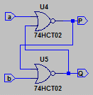
 Run. Simulate.
Readymade filel:  sequence_latchx.asc.
Clocked D-flip-flop (before lab sequence circuits)

What happens to a D-flip-flop that has its D input connected to its inverted output?


![]() Component. 74HCT74.
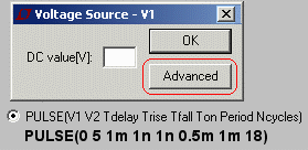
Component. 74HCT74. ![]() Component. voltage. Then Change the voltage source with Advanced and PULSE to get a number of clock pulses.
Component. voltage. Then Change the voltage source with Advanced and PULSE to get a number of clock pulses.
Draw the following schematic:
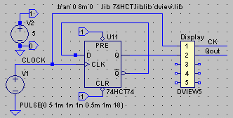
 Run. Simulate. Now you know what happens!
Readymade file:  D_flipflopx.asc
Gray-code up/down-counter ( before lab Sequence circuits )

Started, but not finished file:  gray_counter.asc
Complete the drawing. Connect the input name to the output names, depending on what you come up to under the preparatory task..
 Run. Simulate first with x = 0 and then with x = 1.
Shiftregister-counter ( before lab Sequence circuits )

At the lab, we use a compact circuit 74175 with 4 D-flip-flops, where all the flip-flops reset inputs are connected to the same pin. It is easy to reset the flip-flops, but how does one go about to set them to any value? At the lab, you will learn how to do this by connecting them as a PRBS generator.

Here we instead simulate the shift register counters with the 7474 flip-flops witch have have access to both the PRESET and CLEAR inputs to set the flip-flops to an arbitrary initial state.
Readymade file:  ring.asc.

You can set other start sequences by editing the INIT signal to different PRE and CLR inputs..
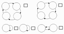
Readymade file:  moebius.asc.
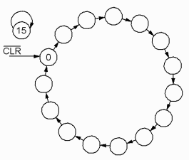
Readymade file:  prbs.asc.
Good luck with the lab preparations!
