Background
In our Swedish academic environment, our projects are, for the most part, funded by government agencies (such as Energimyndigheten or Vinnova), rarely by direct industrial contributions without intermediary agencies, and almost never with KTH internal funds.
In other words: there is no space for projects that do not respond to a direct call from the agencies or a request from the industry. Luckily, we can still shape our ideas and beliefs within the funded projects. Still, the idea that academia is free to conduct any research is baseless (and offensive to the work we put into securing funding).
Given this background, however, we are not a weathervane that turns to align with the way the wind is blowing. Some things are worth pursuing in the name of technology development and environmental conservation. Others are not. There are two crucial staples in our EMD team:
- We are searchers and not re-searchers. In other words, we search for scientific solutions to a problem, and we do not re-search it. When we find a solution, we publish it. We leave re-search and the corresponding acts of journalism or histrionic performances to someone else.
- We develop people of science, who can understand the scientific area they are working in, feel its development, read the trends in the multi-faceted industrial scenario, and be proactive with scientific roadmaps. We do not develop monkeys for the infinite monkey theorem.
Current search focus
In the latest development of the EMD team, we have five main search areas with people actively working in them:
- Analysis and control of variable phase-pole drives;
- Condition monitoring of electric drives;
- Design of electric machines for hydrofoil electric boats;
- Design of high-voltage electric machines for heavy-duty electric vehicles.
- Automatic commissioning of electric drive parameters.
These areas are dynamically changing, partly because people come and go, and partly because of the ongoing trends.
A brief description of the five areas is given here below.
Analysis and control of variable phase-pole drives
Sometimes you stumble on something that shakes your understanding of electric machines and drives. Variable phase-pole drives are one such example.
What are variable phase-pole drives?
Essentially, electric machines changing the number of pole pairs (and phases as a probable consequence) during real-time operation by means of electronic switching.
…and why would you do that?
There is a class of applications where the requirements on torque and speed are pretty wide. Take electric traction for example. You would like a vehicle with strong acceleration features at low speeds, which turns out to be a high torque requirement for the propulsive motor(s). At the same time, once you are running at cruising speed on the highway, the desire is to have motors that deliver the required low torque at high speed with the least electric losses.
Such requirements are very hard to fulfill with conventional electric machine design with fixed numbers of pole pairs. You can stretch out the performance of certain machine topologies, trying to cover the whole torque-speed map. However, the typical high pole number required for high torque at low speeds decreases the energy efficiency at cruising speed. You can certainly design and manufacture an electric machine that delivers the torque-speed map you desire, but there is always the feeling that the blanket is too short: some parts of the map are not well covered.
If you pass the streets of Stockholm, you will certainly notice the advent of electric cars. In many ways, it is a commendable development because it improves the local air quality and reduces the emission of greenhouse gases. Most car and truck manufacturers have turned their heads towards the permanent-magnet synchronous machine (PMSM) to “fill” the torque-speed maps using a small machine capable of delivering high continuous power. This appears all good at first glance, but when scratching the surface, some concerns emerge. First, new drive cycles such as the WLTP, spend more time at low torques and high speed. This is unfortunately the area of the torque-speed map where the efficiency of the PMSM suffers. Second, permanent magnets are not just any material and as the main actor of the show, they are both quite sensitive, unfriendly, and expensive artists. Demagnetization of the permanent magnets due to faults and excessive temperatures is a real issue that, at the very least, irreversibly degrades the machine’s performance and, at worst, could bring you to a halt. Moreover, extracting ores for the strongest magnets is a dirty process resulting in loads of chemical waste and air pollution. On top of that, procurement managers are having nightmares about the supply situation with very limited options of suppliers available.
Among the different attempts that people around the world are looking into to solve these issue, we have embarked on this variable phase-pole approach. These are the ingredients:
- An induction machine with a cage rotor;
- A stator winding split in many independent windings. How many? It depends on the pole change you want to achieve.
- A frequency converter with as many legs as the number of independent windings. Half-bridge legs are sufficient.
The machine is operated in this way. The magnetomotive force generated by the currents in the independent windings is controlled in order to generate the waveforms with the required number of pole pairs while fulfilling the torque and speed references. That is all.
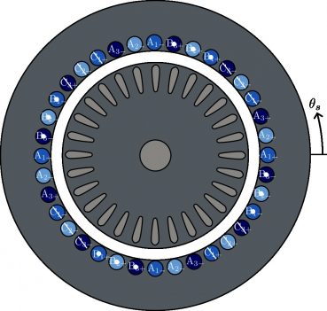
Between the switchings of the different pole-pair configurations, the current distribution in the stator slot might look something like the pictures below. When your windings are connected to guarantee the same current in slots belonging to the same phase, controlling the phase currents is a piece of cake. On the other hand, your hardware simply won’t let you choose between configurations in most cases. If each slot would be individually supplied, things get a bit trickier, but your smorgasbord of options becomes ever so tasty.

It sounds easy, but if you dig into it, you will discover that you need to learn multiphase machines and drives theory, and that would not be enough. You need to lay down another theory on top of that, to understand how to switch the number of pole pairs in real time.
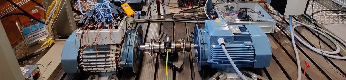
We have done that and built a bench like the one shown in the picture here below. This bench is an extreme example of independent windings since we have chosen to have one independent current for each slot in the stator (in our case, 36 slots and thus 36 independent currents). We can accomplish a controlled switch of pole pair numbers in a myriad of combinations and you would not hear anything if you are beside the bench.
Enjoy our seminal publications on the following topics if you want to know more about this exciting topic:
- Current control and pole change
- Modelling of variable phase-pole machines
- Pole-transition under open phase-faults
- Parameter estimation
Condition monitoring of electric drives
Electric machines die, did you know that? And if you are feeding them with pulse-width-modulated voltages, they will die younger.
This poses a serious problem since it is pretty hard to estimate when your machines are actually going to fail. And you do not want your industrial process, or robot, or electric ambulance to suddenly stop and leave you in dire straits.
There is significant activity around this topic, trying the most disparate ways to estimate the lifetime of an electric machine. Here at KTH, we decided to go for a path that would allow us to monitor it progressively during its operating lifetime. It is difficult but worth the attempt.
The underlying concept is that in many cases the fault develops as a thermal breakdown after a local short circuit in the stator windings (basically: the machine burns). The short circuit is induced by the failing insulation around the windings. So if you want a culprit, blame the insulation.
How to evaluate the insulation degradation? Among the different possibilities, we are looking into methods that monitor the degradation by indirectly monitoring the change in parasitic capacitances of the stator windings. Those parasitic capacitances are related to the dielectric properties of the insulation, and thus they change when the insulation is degrading. In practice, the parasitic capacitances become smaller as the motor is ageing.
How to monitor the parasitic capacitances, then? In principle, you can measure them with special equipment when the machine is still. However, we do not want that: we want the machine to continue its operation while we monitor its insulation state. And here is the fun part: the pulse-width-modulated voltages from the frequency converters are actually exciting the parasitic capacitances. You can notice that by zooming in with an oscilloscope when a switching device goes on or off:
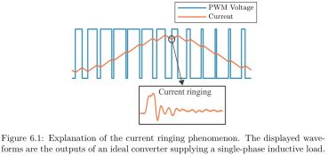
Here are some real measurements as example:
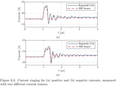
Those oscillations, which go on for very few microseconds, are not noise. It is the resonance effect between the inductances in the machine and the parasitic capacitances, caused by the quasi-squarewave voltage applied at the machine terminals.
So! If you monitor those oscillations and record the change in shape/amplitude over time, you have your insulation degradation monitoring. Easier said than done.
The problem is that those oscillations are very difficult to sample (we are talking about at least 5 MHz of spectral range). In addition, the rules on how they change over time as a function of the insulation degradation state are basically unknown.
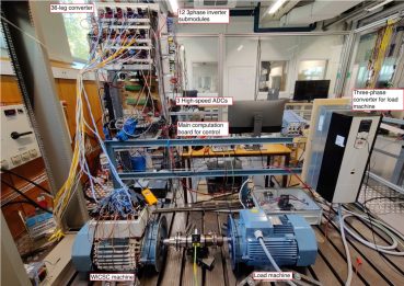
Since we are a bunch of destroyers, we tried to look into one case anyway. Our bench is here below. The machine under test was aged in an accelerated fashion by overloading it while recording the high-frequency oscillations to find the descending trend of parasitic capacitances. It took approximately six weeks of continuous overloading to kill the machine while sucking out of the laboratory all the fumes coming from melted materials.
Are you interested in the results? Look at the doctoral thesis of our Knight Giovanni Zanuso.

Design of electric machines for hydrofoil electric boats
This is a new, exciting field where there is a lot to discover. Marine applications of electric machines and drives are manyfold but – to many extents – still unexplored. The reason? Well, the electrification of the marine industry is far more complicated than the electrification of road vehicles. The energy challenge posed by cruising in the water is not comparable to the “cruising through the air” of conventional road vehicles. Water resistance simply kills your batteries (or fuel cells if you like it so).
However, there are smart people that think differently. Instead of pushing through the water with a conventional boat, why not lift the boat a little bit and drive with the hydrofoil concept? That would reduce significantly the water resistance and thus reduce considerably the need of energy storage on board the boat.
You can imagine that electric hydrofoil boats require a significant all-around effort from aerodynamics, mechanics, materials, control, and electromagnetics. We are just involved in this last part of the chain. Still, a meaningful one: the machine and the converters powering the boat are fully responsible for the propulsion in the water and above the water.
The challenges here involve the design of thin, long machines that reduce the water resistance while delivering significant power to lift the boat above it. At the same time, the design and placement of converters (above the water line, or below it?) and the flexibility of the control algorithms are not pieces of cake. We are on it since the end of 2022 – results coming soon!
Design of high-voltage electric machines for heavy-duty electric vehicles
We have now gotten some solid financing to investigate the next steps in the electrification of road vehicles. When it comes to heavy-duty electric vehicles (like large trucks), the requirements are pretty high: absolutely minimal losses in the entire drivetrain, fast charging capabilities, high power ratings with high torque at low speeds and low torque at (cruising) high speeds. In addition to very simple demands like 10x more lifetime than a conventional passenger car, and reliability close to 100%.
For all the reasons above, we are observing a shift towards higher voltages in the heavy-duty vehicles. For a given power range, higher voltages reduce the currents, which reduces losses. It also potentially enable faster charging times. Regarding torque-speed and reliability, well: it is all to explore. That is why we are here.
We are soon starting this project under this years 2023. Tune in later this year for more information!